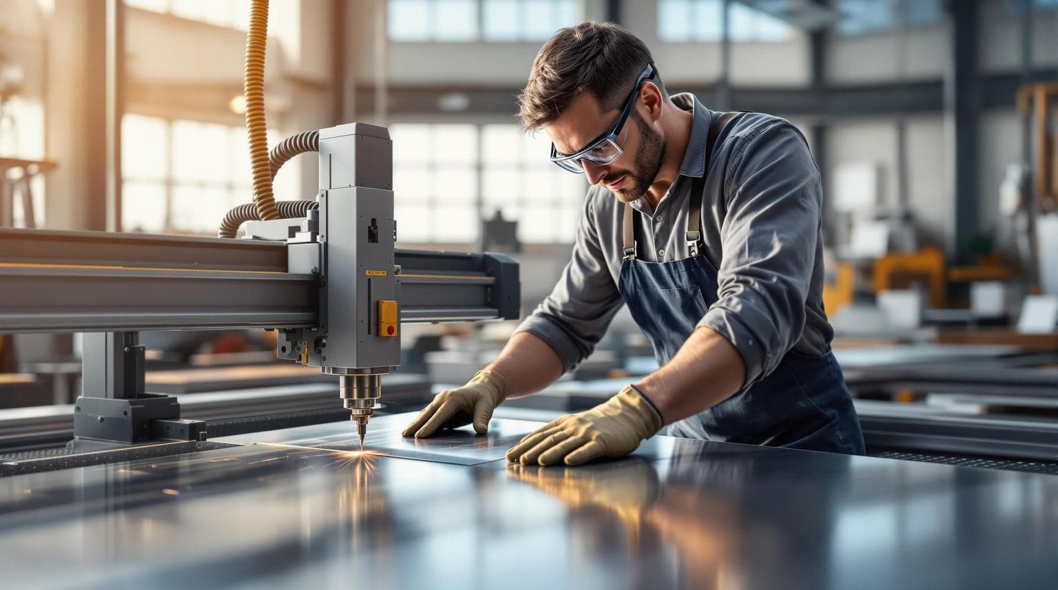
8 Common Sheet Metal Fabrication Mistakes to Avoid
Sheet metal fabrication mistakes can lead to costly rework and material waste. Avoiding these errors is crucial for maintaining precision and controlling costs in industries like automotive, aerospace, and mining. Here’s a quick summary of the most common mistakes and how to prevent them:
- Wrong Material Selection: Using incorrect materials can result in high scrap rates and rework costs. Always match materials to performance needs and environmental conditions.
- Poor Feature Placement at Bends: Features placed too close to bends can weaken parts. Follow the 4T rule (4x material thickness) to maintain structural integrity.
- Incorrect Springback Calculations: Misjudging springback leads to dimensional errors. Use forming simulations and proper compensation techniques.
- Missing or Wrong Bend Relief: Poor relief design causes stress and part failure. Adhere to standards like AS/NZS 5131 and use simulations to optimize relief patterns.
- Wrong Tool and Equipment Use: Incorrect tools increase defects and wear. Choose tools suited to the material and maintain them regularly.
- Metal Grain Direction Errors: Ignoring grain orientation weakens parts. Verify grain direction during design and fabrication.
- Metal Wrinkling and Buckling: Improper pressure or alignment leads to surface defects. Use real-time monitoring tools and adjust forming processes.
- Poor Post-Process Quality Checks: Skipping inspections results in missed defects. Implement thorough quality control systems and advanced inspection tools.
Quick Overview
| Mistake | Key Issue | Solution |
|---|---|---|
| Wrong Material Selection | High scrap rates, rework costs | Match materials to needs, follow standards |
| Poor Feature Placement | Weak structural integrity | Follow 4T rule, use design tools |
| Incorrect Springback | Dimensional errors | Use simulations, adjust compensation |
| Missing/Wrong Bend Relief | Stress, part failure | Optimize relief design, use standards |
| Wrong Tool Use | Increased defects, tool wear | Select proper tools, regular maintenance |
| Grain Direction Errors | Weakened parts, fractures | Verify grain direction, adjust tooling |
| Wrinkling/Buckling | Surface defects | Adjust pressure, use monitoring tools |
| Poor Quality Checks | Missed defects, high rework costs | Implement advanced inspection systems |
5 Common Sheet Metal Design Mistakes to Avoid
1. Wrong Material Selection
Choosing the wrong materials can lead to serious issues. For example, using incorrect steel grades results in a 23% scrap rate, with rework costs averaging $150 per hour.
Material Considerations for Australian Conditions
Australia's climate adds extra challenges when selecting materials. Coastal areas, for instance, demand materials that can handle marine environments. Zinc-coated steels last three times longer in these regions compared to untreated alternatives. A Perth-based automotive parts manufacturer learned this the hard way. They used mild steel instead of AR400 for truck brackets, leading to a $48,000 recall in just six months.
Matching Materials to Performance Needs
Different industries have specific material requirements. Here’s a quick guide to recommended materials and common mistakes:
| Industry Sector | Recommended Material | Key Needs | Common Mistake to Avoid |
|---|---|---|---|
| Food Processing | 316L Stainless | Corrosion resistance | Using 304 grade (lacks chemical resistance) |
| Mining Equipment | Hardox 450 | Abrasion resistance | Using standard steel plate |
| Architectural | COLORBOND® steel | UV/weather resistance | Using non-coated alternatives |
| Automotive | DP600 Steel | Strength-to-weight ratio | Using CRCA steel for structural parts |
The Cost of Getting It Wrong
Material mistakes can be expensive. Dr. Helen Tan highlights the importance of accelerated aging tests to simulate real-world conditions and avoid costly errors. A Sydney hospital, for instance, specified 304 stainless steel for surgical carts instead of 316 grade. The result? Premature pitting corrosion and full replacements within two years, which disrupted precision requirements critical for aerospace components. On the other hand, Melbourne fabricators used predictive material modeling to save 18% on costs.
Standards to Follow
To ensure quality, adhere to these Australian standards:
- AS 1397: Continuous hot-dip metallic coated steel
- AS/NZS 1734: Stainless steel grades
- AS 3678: Structural steel
"Invest in DFM software with material libraries"
Aluminium 5052, though $2.50/kg more expensive than Galvabond®, offers long-term savings by preventing coastal corrosion.
2. Poor Feature Placement at Bends
Choosing the right material is just the first step - how you design around bend zones plays a huge role in structural integrity. The 4T rule is a key principle here: features like holes or notches must stay at least 4 times the material's thickness away from bend lines.
Key Distances to Know
Different materials have unique requirements when it comes to maintaining safe distances from bends. Here's a quick reference:
| Material | Thickness | Minimum Safe Distance |
|---|---|---|
| Mild Steel | 1.2mm | 4.8mm |
| 5052 Aluminum | 2mm | 8mm |
Why Poor Placement Matters
Placing holes or features too close to bends can lead to deformations of ±0.5–1.2mm. This not only exceeds ISO 2768 standards but also cuts fastener strength by 25%. For example, EV battery enclosures often demand precision within 0.3mm, making poor placement a major risk. A Sydney-based auto parts supplier demonstrated the importance of validating feature placement, reducing first-article defects by 68% through careful design checks.
How to Avoid These Issues
Using advanced DFM (Design for Manufacturability) tools can help eliminate feature placement errors. These tools offer:
- Real-time collision detection during virtual bending processes
- Stress maps to highlight areas at risk
- Automated clearance checks to ensure compliance with 4T and 6T rules
For intricate designs, these practical techniques can help:
- Offset holes instead of placing them in straight lines near bends
- Use oval-shaped relief cuts for features within 6T zones
- Add tolerance buffers of 0.5–1mm for laser-cut features in bend areas
In high-precision industries like aerospace or automotive, experts also recommend conical countersinks over flat-bottomed holes near bends. These methods not only improve feature placement but also directly impact springback performance, which we'll dive into next.
3. Incorrect Springback Calculations
Accurate springback calculations are key to achieving precise dimensions in metal fabrication. In Australia, where tight tolerances are the norm, uncontrolled springback can lead to components failing to meet AS/NZS 1554.1-2024 standards.
Understanding Springback Impact
Springback varies with material type. High-strength alloys typically need an overbend of 5°-10°, compared to 2°-5° for mild steel. For example, a Sydney aerospace supplier managed to achieve an impressive ±0.25° accuracy using Dynaform simulations.
Material-Specific Compensation Factors
Each material demands tailored compensation methods:
| Material | Springback | Compensation Approach |
|---|---|---|
| CRCA Steel | 15% | Standard overbend |
| Stainless Steel | 25-30% | Enhanced overbend + coining |
| High-Strength Alloys | 35-40% | Compensation calculated using FEA |
Environmental Considerations
Australia's climate presents unique challenges for fabricators. Coastal humidity, for example, can increase springback in uncoated steels by 0.5°-1.2°. Darwin workshops have reported needing 12% more compensation than those in Melbourne during the wet season.
To address these challenges, top Victorian manufacturers employ strategies like:
- Material certification with yield strength data, which has reduced springback errors by 90%.
- Weekly press brake calibration using test coupons.
- Coining dies and reduced die clearance (≤8% of material thickness), improving accuracy by 18-22%.
"The difference between success and failure in high-precision sheet metal work often comes down to understanding your material's springback characteristics and implementing the right compensation strategies", says a leading Victorian manufacturer who reduced errors by 90% through systematic material testing and compensation.
Springback adjustments also tie closely to bend relief design, which will be discussed in the next section.
4. Missing or Wrong Bend Relief
Bend relief design plays a crucial role in managing residual stresses, especially when compensating for springback. According to AS/NZS 5131 standards, poorly designed bend relief is a leading cause of quality issues in Australian manufacturing.
Key Design Factors
Bend relief distances must often go beyond the standard 4T rule for critical applications. Material properties and grain direction are important considerations when determining relief requirements:
| Material Type | Minimum Relief Distance | Additional Notes |
|---|---|---|
| Standard Steel | 4T | Basic relief design |
| Stainless Steel | 6T | Requires extended patterns |
| Aerospace Grade | 5T (125% of standard) | Needs full documentation and testing |
Common Problems
In a Melbourne study, undersized reliefs in 3mm steel resulted in a 23% rejection rate. This issue is even more severe in automotive manufacturing, where missing reliefs caused a 15% premature failure rate in truck chassis brackets.
Advanced Solutions
Top Australian fabricators are tackling these challenges with the following methods:
- Dynaform Simulation: Achieves a 40% reduction in defects (medium cost).
- PLM Validation: Prevents 65% of errors (high cost).
- DFMEA Checklists: Ensures 85% compliance with minimal investment (low cost).
Sequencing for Better Results
A Perth-based manufacturer found success by rethinking their bending sequence. By reversing the order of bends in complex multi-bend parts, they reduced the need for large reliefs by 35%. This adjustment saved $28,000 annually in material rework.
"The difference between a successful bend and catastrophic failure often comes down to proper relief design. Our implementation of teardrop-shaped reliefs instead of rectangular ones reduced stress concentration points by 78% in high-stress applications", shared a leading Sydney fabricator.
This approach complies with aerospace tolerances under NATA certification. Fixing issues after production increases costs by 18-35% compared to addressing them during the design phase.
Proper tool selection also plays a critical role in these strategies, which will be discussed in the next section.
sbb-itb-ce80a9d
5. Wrong Tool and Equipment Use
Choosing the right tools is essential for maintaining fabrication quality and controlling costs. In Australia, this becomes even more critical due to the challenges of remote maintenance and strict export certifications. Errors in tooling can lead to dimensional inaccuracies beyond the acceptable +/- 0.5mm tolerance.
Common Equipment Challenges
An in-depth look at Australian fabrication shops highlights three major equipment issues:
| Issue | Impact | Solution |
|---|---|---|
| Using general-purpose dies on high-strength steels | 18% higher tool wear | Selecting dies tailored to the material |
| Manual folding for aerospace parts | 0.3° angular errors | Switching to CNC-controlled bending |
| Incorrect punch clearance | Burrs exceeding 10% of material thickness | Automating clearance adjustments |
Material-Specific Tooling Needs
Different materials bring unique demands. For example, stainless steel requires tools with 20% higher tonnage capacity compared to mild steel. Aluminum components, on the other hand, need polished carbide tools to prevent adhesion problems.
Advanced Technology in Action
Many Australian fabricators are turning to advanced technology to reduce tool-related mistakes. A Brisbane aerospace manufacturer shared their success with IoT-enabled torque monitoring:
"Our implementation of digital torque monitoring systems reduced fastening errors by 62% in critical aircraft components, saving approximately A$85,000 in quarterly rework costs", said the facility's chief engineer.
Maintenance Matters
Regular maintenance plays a huge role in keeping production efficient. A Sydney HVAC manufacturer found that worn turret punch components caused a 15% increase in rejected panels. They addressed this with a structured maintenance program:
| Action | Result |
|---|---|
| Weekly digital calibration | 25% faster production cycles |
| Daily tool monitoring | 40% reduction in rejects |
| Surface finish inspections | 98% first-pass yield rate |
Guidelines for Die Selection
Choosing the correct die is crucial. The formula V = (6-12) × material thickness helps guide the process. A Perth architectural firm learned this the hard way when using a die with V=6t instead of V=8t for 2mm stainless steel, leading to a full rework of their project.
The Importance of Training
Investing in proper training can significantly improve outcomes. Melbourne manufacturers who aligned with MEM30205 training standards reported:
- 60% fewer setup errors
- 40% longer tool life
- 98% first-pass yield rates
In one case, a mining equipment fabricator introduced digital height gauges with ±0.01mm accuracy after a costly A$120,000 rework incident.
Proper tool selection also sets the stage for managing material grain direction - an essential factor we'll dive into next.
6. Metal Grain Direction Errors
Getting metal grain direction right is key to achieving accurate forming results. Studies reveal that neglecting grain orientation can lower tensile strength by 15-20% and lead to up to 30% variation in elongation capacity.
Impact on Material Properties
The effects of ignoring grain direction vary by material. For example, a Perth automotive manufacturer faced consistent fractures in their 90° brackets, which caused an 18-22% increase in scrap rates.
| Material Type | Impact of Wrong Grain Direction | Required Adjustment |
|---|---|---|
| Aluminum Alloys | 30% drop in ductility | Increase bend radius |
| Stainless Steel | Uneven edge warping | Adjust brake pressure |
| Titanium Alloys | 40% directional differences | Use specialized annealing |
Verification Methods
To avoid grain-related defects, modern Australian fabricators rely on three key verification steps:
| Stage | Method | Accuracy |
|---|---|---|
| Pre-fabrication | Digital microstructure analysis | 98% |
| Setup | Directional scratch test (10x loupe) | 95% |
| Production | Test bend analysis | 92% |
Advanced Solutions
Manufacturers are increasingly using advanced tools to tackle grain direction issues. Software like the SolidWorks Sheet Metal module and AutoForm® forming simulations now include material orientation flags, which have significantly reduced defects.
"Our implementation of AS 4100 standards has reduced rejection rates by 62% in aerospace components", says a quality control manager at a Brisbane-based manufacturer.
Material-Specific Considerations
Special care is needed for aerospace-grade titanium parts, as their strength can vary by up to 40% depending on the grain direction - a much greater difference than standard steel.
Quality Control Protocols
TAFE NSW certification now emphasizes interpreting material certifications, adjusting tooling based on directional properties, and following AS 5040 heat treatment protocols.
These grain direction protocols are critical for managing stress distribution, which plays a major role in avoiding wrinkling and buckling - topics we’ll explore next.
7. Metal Wrinkling and Buckling
Wrinkling and buckling are major culprits behind costly rejections in manufacturing. In fact, these defects make up 38% of automotive manufacturing flaws in Australia, posing serious challenges for fabricators.
What Causes Wrinkling?
Wrinkling happens when compressive strain becomes too much for the material to handle during forming. For example, in automotive body panels, insufficient binder pressure often leads to creases along the flange areas. Thin materials, especially those between 0.6-1.2mm, are at a much higher risk - 40% more likely to wrinkle compared to thicker materials.
Industry Standards and Expectations
Different industries have specific tolerance levels for surface defects. Here's a quick breakdown:
| Industry Sector | Tolerance Requirements | Standard Reference |
|---|---|---|
| Aerospace | ≤0.1mm surface deviation | AS/NZS 1554.3 |
| Automotive | ≤0.5mm/m waviness | Company-specific |
| Mining Equipment | Variable (non-structural) | AS 2317.2 |
How to Prevent Wrinkling and Buckling
A great example comes from a Geelong-based automotive parts manufacturer. They were dealing with frequent buckling in their HVAC duct production. By using Haas HT210 hydraulic cushion systems, they managed to cut rejection rates by 68%.
Tools for Real-Time Monitoring
To tackle these issues, many Australian workshops are using advanced diagnostic tools. Here's a look at some of the most effective options:
| Tool Type | Application | Accuracy Rate |
|---|---|---|
| Laser Analyzers | Real-time strain distribution | 95% |
| AutoForm Software | Die design simulation | 92% |
| Digital Surface Mapping | Post-forming inspection | 89% |
Quick Fixes for Wrinkling During Production
If wrinkles appear mid-production, follow these steps:
- Increase blank holder pressure in 10-15% increments.
- Use a Teflon-based lubricant to minimize friction.
- Check punch-die alignment, ensuring a tolerance of 0.05mm.
Material Thickness Matters
According to AS 1397 standards, materials used in compression-heavy forming should be at least 1.5mm thick. Electronics manufacturers have successfully reduced rejection rates by sticking to this guideline for thinner materials.
Addressing these defects effectively is crucial for maintaining high-quality production, as explored in the upcoming section.
8. Poor Post-Process Quality Checks
Fixing physical defects during production is essential, but thorough quality checks after fabrication serve as the last line of defense against expensive mistakes. Without these checks, the benefits of using the right materials and forming methods are often lost. Studies reveal that inadequate quality checks result in an average rework cost of 23%, compared to just 6% when proper quality assurance is in place. For aerospace parts, this figure can climb as high as 41%.
Key Areas to Inspect
Post-production checks should focus on verifying:
| Inspection Parameter | Required Tolerance |
|---|---|
| Dimensional Accuracy | ±0.1mm (automotive) |
| Surface Roughness | 0.8-3.2µm |
| Weld Integrity | 27J at -20°C |
| Coating Thickness | <15µm variation |
Advanced Inspection Tools
AI-powered visual systems are now capable of meeting the precision needed for EV battery enclosures, as discussed in Section 1. These systems boast a 99.3% defect detection rate, making them especially useful for parts with complex shapes.
Commonly Overlooked Issues
Some critical inspection points are frequently missed, including:
- Micro-cracks: Often found near bend radii in high-stress areas.
- Coating inconsistencies: A crucial factor for marine applications where corrosion protection is vital.
Effective Quality Control Systems
A modern quality assurance program should include three main components:
-
Digital Documentation and Measurement
- Automated data recording from gauges
- Real-time updates for specifications
- Tracking of revision changes
-
Material Certification
- Full traceability of materials
- Adherence to AS/NZS 1554 standards
-
Final Audit Process
- Verification by a quality control supervisor
- Sign-off by a welding engineer
- Validation of all critical parameters
Training for Inspectors
Senior inspectors should hold Level II NDT certification, which equips them with:
- Advanced skills in non-destructive testing
- The ability to make informed decisions about part acceptance
These quality control measures help ensure that all the effort put into material selection and fabrication results in dependable, high-quality products.
Material and Tool Requirements Table
Avoiding fabrication errors starts with meeting precise material and tool specifications:
Material-Specific Requirements
| Material Type | Thickness Range | Min. Flange Height | Die Width Ratio | Press Brake Tonnage |
|---|---|---|---|---|
| Mild Steel (AS 1397) | 0.8-2.0mm | 4x thickness + bend radius | 6:1 | 12 tons/meter |
| Stainless Steel | 2.0-3.0mm | 5x thickness + 1mm | 4:1 | 22 tons/meter |
| Aluminum (5052) | 0.5-1.2mm | 4x thickness + bend radius | 8:1 | 8 tons/meter |
Tool Specifications and Clearances
| Application Type | Required Tolerance | Tool Coating | Minimum Distance Between Features |
|---|---|---|---|
| Commercial | ±0.2mm | Standard Steel | 3x thickness + 0.5mm |
| EV Components | ±0.1mm | TiN-coated | 4x thickness |
| Defense Systems | ±0.05mm | Specialized | 5x thickness + 1mm |
Material-Specific Processing Requirements
| Material | Lubrication Type |
|---|---|
| Structural Steel | Dry-film coating |
| Aluminum Alloys | Water-soluble synthetic |
| Stainless Steel | Chlorinated oils |
These specifications align with wrinkle prevention methods in Section 7. For aerospace parts, tool alignment must achieve a maximum deviation of 0.01mm/m as per AS 2536 standards. Food-grade applications require NSF H1 certified lubricants, while marine components demand extra corrosion protection per AS 1449 standards.
Summary and Next Steps
By addressing these eight key errors, manufacturers can take actionable steps to improve fabrication processes. Research from Australian manufacturers indicates that adopting effective error prevention strategies can cut defect rates by up to 58% within six months.
Here’s how top Australian manufacturers tackle these challenges systematically:
| Stage | Actions | Results |
|---|---|---|
| Immediate Response | Use AI-driven forming simulation | 65% fewer trial runs |
| Process Enhancement | Implement ISO 9001 quality gates | 15-25% drop in scrap rates |
| Continuous Monitoring | Conduct monthly tool wear audits | 72% fewer weld failures |
Experts working on material selection and tooling issues (Sections 1-5) can assist with:
- Material certification analysis
- Custom K-factor tables
- Advanced springback prediction models with ±0.25° accuracy
To maintain these improvements, manufacturers should rely on industry standards like AS/NZS 1554.1:2021. These frameworks support the inspection protocols discussed earlier and incorporate verified error pattern databases, enabling manufacturers to apply the springback solutions detailed in Section 3.